
Precision measurement and adaptive solutions for high-quality stator production in powertrains
Batteries or fuel cells provide the energy. The drive train ensures that the wheels move. The drive train can be subdivided into the electric motor, consisting of stator and rotor, and the power electronics. Especially in the production of stators, our products are used in numerous manufacturing steps.
For example, the thicknesses of the lacquer layers of the copper wires are measured inline and directly after decoiling. The detection of varnish residues after paint stripping and before laser welding is also crucial for high laser welding quality. This is because if paint residues are still present, they melt during laser welding and can lead to the formation of pores. The required bonding cross sections could then no longer be guaranteed.
But laser welding also calls for innovative solutions. The pins to be welded sometimes have different heights, the individual pins can also be twisted in the plane and there can be gaps between the pins. Pins can be cut differently, and reflections from the clamping device also do their part. To meet these challenges, we have adapted our products to adaptively adjust the laser welding process at any time and quickly: for the highest quality in stator production.
Solutions for your manufacturing steps in powertrain

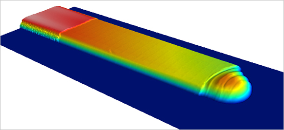
Defect-free hairpin surfaces are crucial for reliable electrical insulation in electric motors. Hairpins consist of copper wires that are coated with a protective polymer coating. This insulation layer must be free of defects in order to prevent short circuits or voltage breakdowns.
Typical defects are blisters, chipping, cracks or scratches in the coating. Such surface defects impair functionality and must be detected at an early stage.
Our high-precision in-line sensor technology (CLS 2 Pro and CVC) enables 100% inspection of hairpin surfaces in real time - directly integrated into the production line and cycle time-neutral. The system reliably detects any defects and the measurement result is available immediately. This means that faulty hairpins can be ejected from the process at an early stage and in a targeted manner.
The result: assured component quality, greater process reliability and sustainably optimized production efficiency. In addition, the complete documentation of the measurement results ensures the seamless traceability of every single hairpin wire.
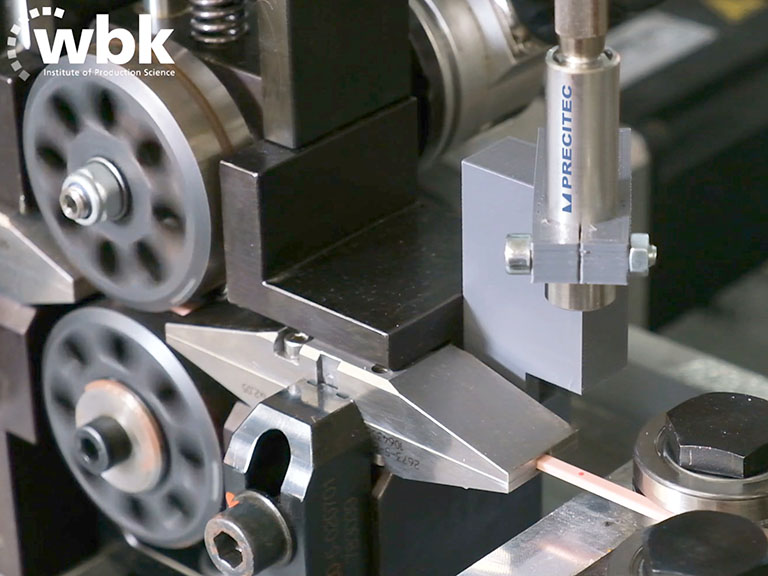
Hairpin technology is a central component of modern stator production for electromobility. In this process, bent copper wires, known as hairpins, are coated with an insulating layer of polymers. The thickness of this coating plays a decisive role in the production process.
If it is too thin: insufficient electrical insulation, increased risk of short circuits
If it is too thick: problems during processing, risk of faults in the production system
Our high-precision CHR Mini and CHR 2 IT sensors enable 100% inline measurement of the coating thickness - cycle time-neutral and directly in the production line. This real-time measurement enables wires that are coated too thinly to be detected at an early stage and ejected from the process before they are installed in the stator. This not only ensures the quality of the manufactured components, but also increases the efficiency of the entire production system. In addition, the complete documentation of the measurement results enables full traceability of each individual hairpin wire.
Robust laser welding processes for stators - AI-supported image evaluation and adaptive process control
For electric drive technology in electromobility, series production of traction motors must be flexible and feasible in large quantities. This requires high-precision and robust manufacturing systems for the stator, rotor and power electronics.
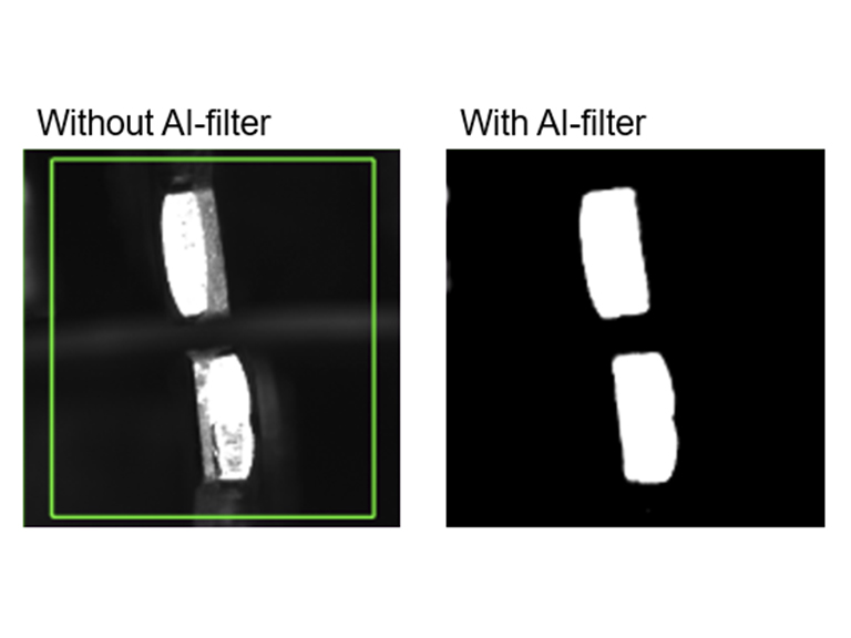
In the production of stators based on hairpin technology, copper wires are cut, bent, inserted into the grooves, twisted and then laser-welded. A key challenge in laser welding is the reliable component position detection of the hairpin pairs. Depending on the cutting technology and the position in the scan field, differently exposed gray images are created, which make exact pin recognition difficult.
Our AI-supported image evaluation converts these gray images into binary black and white images. This allows the pin contours to be recognized precisely, enabling exact positioning and adaptive tracking of the laser beam in the x and y directions.
The ScanMaster is a particularly powerful solution. This system combines robust component position detection with high-precision distance measurement to the workpiece surface (z-position), auto-focus for z-correction and integrated process monitoring.
Find out more about the ScanMaster
The process is monitored by the Laser Welding Monitor LWM, which detects welding anomalies in real time and with a 100% inspection rate, regardless of the cycle time. This ensures a reproducible and high-quality welded joint with high electrical conductivity. At the same time, a large connection cross-section, minimal spatter formation and a significant reduction in porosity are achieved.In addition, our LWM-KI has been successfully implemented for the laser welding of hairpins. It enables the automated classification of the defect type in the event of a faulty weld, for example in the case of laser power errors, focus position errors, contamination or comparable deviations.
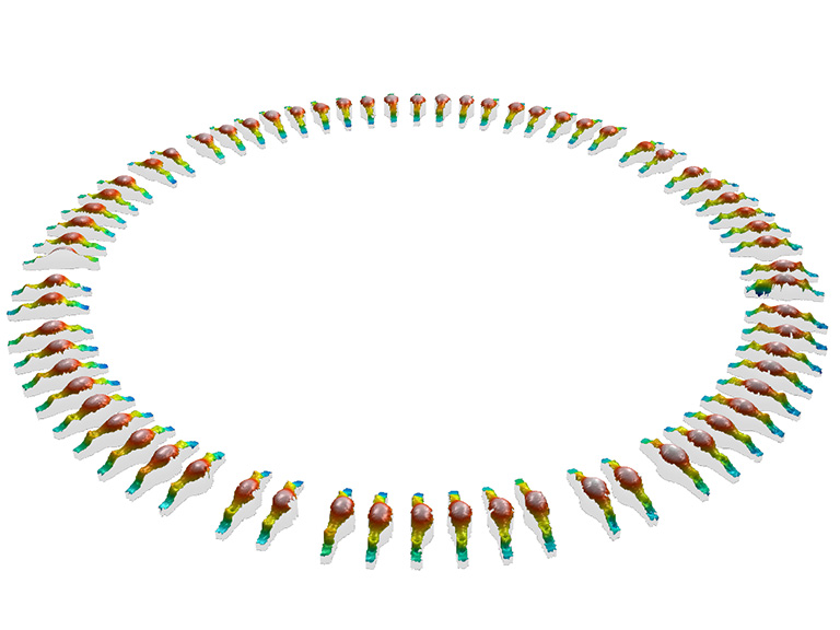
After laser welding, quality-relevant features must be measured precisely. One decisive parameter is the air gap - the distance between the welded pin pairs. If this distance is too small, voltage flashovers can occur, which jeopardizes electrical safety.
Another important criterion is the shape and position of the welding tip. If the weld tip is tilted or has topographical anomalies, this indicates a faulty welded joint.
Our Flying Spot Scanner 310 provides a high-precision solution for capturing the 3D topography of the entire stator quickly and reliably. The sensor works on the basis of OCT technology (optical coherence tomography). The OCT beam is deflected highly dynamically via galvo mirrors in order to capture the complete geometry of the stator in detail. A telecentric lens also ensures maximum measurement accuracy over the entire field of view.
We were recently awarded the Innovation Award for the Flying Spot Scanner 310.
Further fields of application in e-mobility
Fuel cell
A fuel cell consists of numerous bipolar plates that have to be welded gas-tight. In most cases, the welding speeds are very high - as are the quality requirements for the weld seam. In addition, the geometric parameters of the bipolar plates must be precisely maintained to ensure high fuel cell performance. We measure these with our 3D measurement technology sensors.

